Board Stuffing
At this point, it goes without saying that you should already know the difference between a resistor and capacitor, how to tell them apart, and how to orient polarized parts. Fortunately, K&K has provided written instructions, schematics and pictures. You might need to Google an image to see what the part is supposed to look like. A Google image search of “220uf 160V” will give you pictures of various capacitors from different manufacturers, but they look very similar, and the values of electrolytic capacitors are conveniently spelled out on the body of the capacitor. On the other hand, resistors usually have “color bands”, or some bizarre arcane numbering system. Only God knows why they can’t put “1K” or “47K”. The instructions help decipher which set of color bands and numbers correspond to which resistor. Also, there are polarities to observe on some of these components: The rectifiers and electrolytic capacitors can only be inserted in one specific orientation, or you will destroy something. The same applies for the six voltage regulator transistors; there are 6 of these that can be turned the correct way or the incorrect way—pay attention.
Read the directions, and fit the parts to the PC board in the order given by K&K. This keeps you from putting on something that will get in the way of other components as you add more parts. After you have determined which part to insert first, you need to find out where the part is. The directions come with a helpful CD Rom and pictures to help you figure out what the parts look like. K&K will refer to a part in the written instructions, which corresponds to the part number in the parts list, the part number in the schematic and the written labels on the PCB. The PCB itself is labeled with the part number, but not the part value. The parts list, besides giving you the part number and the component value, also has visual descriptions of resistors, to help you pick them out. You can look on the schematic and/or the parts list to find out which value is R1, C3, etc., then remove that value from the parts packaging, or the piece of paper if you took my suggestion. In the case of most of the capacitors, you don’t need to bend the leads—they “snap” in place. If you have a component that needs to have its legs bent to fit the board, measure the spacing of the corresponding holes on the PCB. I did this with a set of calipers. You can use a very small ruler or tape measure, if you don’t have a cheap set of calipers. Calipers can be handy to keep around the house, and cheap ones from Asia are accurate enough for this kind of work. Look on eBay.
After measuring the hole-to-hole distance, find the corresponding spot on the lead bending tool, which goes from as little as .40” to 1.5”. Place the component in the slotted side of the lead bender (the 801 has room for ¼ and ½ watt resistors), with the part value showing (so you can see what it is after you install it), then gently push the legs down to form the right angles. Do not attempt to create extremely sharp, right angles, you might damage the metal in the leads from stress fracturing. Push the resistor through the corresponding holes, then verify the spacing required by K&K between the body of the component and the PC board. For power resistors, K&K specifies that you allow some room between the PCB and the body of the component, to allow for cooling. You can use a piece of cardboard or a couple pieces of popsicle stick to allow room for cooling. Except for the power resistors (R1, R4, R114, R115, R214 and R215), I just pushed the body of the component against the body of the board. I then flipped the board over and splayed the leads out. I do this for two reasons: First, splaying keeps the devices from falling out so I can solder multiple devices at one time, and second, it creates a good physical contact between component and PCB. Solder is not glue. Try to get good physical contact between the device, or the wire, and the PCB you are going to solder. The solder prevents oxidation and vibration from contaminating or loosening the electrical contact between the component and PCB trace. Do this for every device, even the tube sockets; you can’t bend the leads of the heat sinks—they are too sturdy.
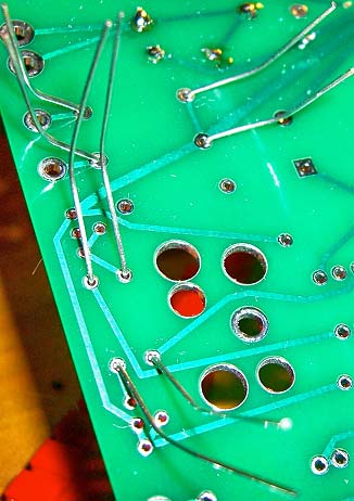
I bent, inserted and soldered about 15-20 pieces at a time, then soldered. That seems to be an efficient way of stuffing these boards. You can completely stuff the board, then solder, but you will have quite a forest of component leads sticking through the PCB.
Soldering Supplies
I recommend that you buy a good soldering iron. Don’t buy one from a hardware store or Radio Shack; instead look for Hakko or Weller brand products. I have been using the Hakko dual wattage iron (20W/130W) and Hakko 599 Tip Cleaner. The heat sinks require a very hot iron. With the Hakko at 130 watts, I was able to solder the legs of the heat sinks to the board. In general, choose a solder that is thin and has a low melting point. You will need rosin core solder, not acid core. Acid core solder is for plumbing, not electronics. The sooner and faster your solder melts the better. If there is a good electrical connection before soldering, the type of solder you use has much less impact on the sound. Again, solder isn’t glue. It has no magical properties. Whatever copper, brass and nickel can do, solder can do much worse. Make sure the part is actually touching the PCB before applying solder. When you start to solder, be sure to tin the tip of the iron, heat the work with the tinned tip, and then apply solder to the work. If the iron is hot enough, the work should heat up quickly, the solder should melt and flow within a second, and the resulting joint will be shiny, with a distinct meniscus, like how water rises up the side of your glass. If all the metal is clean, there is enough heat to thoroughly heat the work and melt the solder, and if there is enough flux, the solder will wick up the work, much like capillary action. In the process, it creates a meniscus.
I worked at this for an hour at a time, and then took a break. When I came back, I would trim the leads as close to the board as possible without getting into the solder joint. Wear glasses! When the bits of wire shear off, they can fly 10-15’, and have enough energy to damage an eye. I didn’t keep track of the time, and it really doesn’t matter how long it took me. Every other person who does this project will be either slower or faster. I prefer to be very deliberate.
You should be careful not to apply heat for too long to some of the parts. Be careful not to keep the soldering iron on the regulator transistors longer than necessary. Be particularly careful if you happen to use polystyrene capacitors. I don’t think they are an option with K&K, so you shouldn’t have any in your kit. Polypropylene and mylar are also susceptible to damage from the soldering iron. Finally, I’m not sure how the wires are attached inside the Lundahl transformers, so solder one joint, go to the opposite channel’s transformer, solder the same joint, jump back to the first transformer, but the opposite side of the first solder joint, etc., going back and forth between the two transformers and the separate sides of the two transformers. That should be sufficient to prevent you from damaging the lead-out wire attachment points, or their insulation.
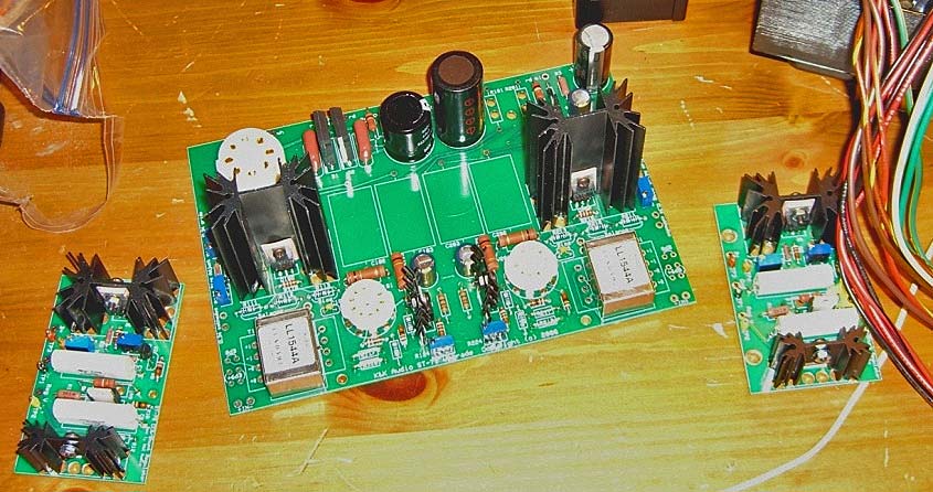
The instructions supplied with the kit were easy to follow. The parts were separated out, so there wasn’t much chance of mixing parts between the regulators and main board. All the parts were of good quality. The boards were double-sided, thick, and clearly labeled, making it easy to figure out where to place the individual components. I think Kevin has done a good job of making this a relatively easy job for the DIY’er with some knowledge of part types and schematic symbols.
If you are unsure about what you are doing, look at the parts list, then the schematic, then the PCB, then the supplied pictures to check your work. If there are still doubts, use a meter to verify you are about to install the correct device. Once installed, it should agree with the supplied pictures. If you are still having problems, get help from a friend, or pay someone to finish the job for you. If you persevere and are successful, you will be surprised how good your own work sounds to you. Just as children all look beautiful to their parents, DIY’ers similarly love their creations.
In the next installment, I will cover installing the transformers, boards, jacks, wiring, output tube selection, initial start up, sound and final considerations, which is still a lot to cover.
- ← Previous page
- (Page 3 of 3)
What ever happened to the third or final part of the K & K Audio power amplifier?
Gary,
I’ve been stagnant with DIY while trying to get a new business up and running. I plan on sending in the final part of the story in early September.
Thank you for your interest.
Regards,
Phillip
Hi Phillip,
I have enjoyed your article which had my attention due to the fact I have been working with Kevin Carter putting together an st70 inspired amp with one or two modifications I required (240 volt and both 4& 8 ohm taps) for which Kevin will provide all the necessary hardware except the valves. This is something new for Kevin as up until now he has only provided the K&K board and shunts.
I was interested to here your third installment, especially you final listening views, and also to hear of anything which may have proved tricky – basically using you as the mine sweeper.
Please let me know how you got on and if in fact you have finished your DIY project.
Regards,
Tim.