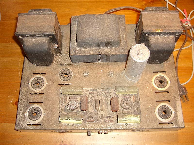
There are at least three possible starting points for this project: You have an existing ST70 in good condition; you have a completely FUBAR ST70 with a few good bits and pieces; or you start with all new parts. If you want to order all new parts, I will post what you will need to duplicate this project in part 3. In my case, I had a smoke damaged, non-working ST70 that already required a complete rebuild. Because the chrome was covered in some kind of nasty crud from the fire, mixed with rust, I had the choice of paint, powder coating, or chrome plating, or a combination of these. I chose to sand blast, then powder coat in silver or gray hammertone, which provide a very durable, attractive and forgiving finish (forgiving of imperfections in the old chassis).
Tear Down of an Existing Unit
There are a few tools to gather together if you are demolishing an old unit:
- Slotted screw driver
- Drill with ¼” to 5/16” drill bit (choose a bit that is strong to prevent breaking, and long enough to give some room between the chassis and the drill chuck)
- Wire cutters
- Large needle-nose pliers (the short and stout version)
- Heavy cotton, or leather, gloves
- Newspaper, or old towel, to collect the bits and pieces of crap that will fall out of the unit, none of which you want on your floor or clothes
- Safety glasses (reading glasses will do in most cases)
- Nitrile gloves to keep your hands clean if the unit is disgusting (or heavy paint stripping gloves from the home improvement store)
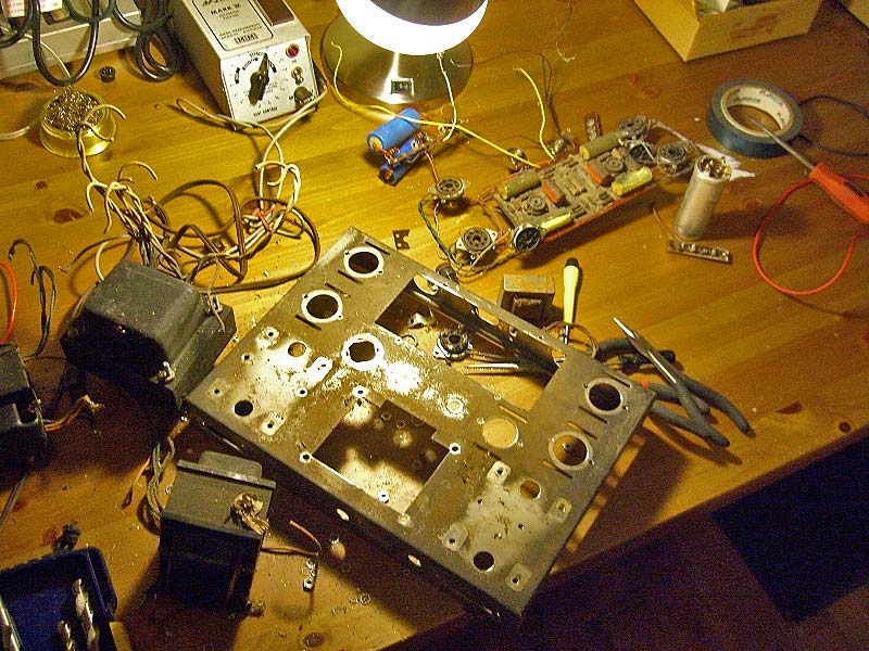
If yours is old and dead, like this one was, you will need these basic tools to disassemble the ST70. It took me 15 minutes to completely demolish the unit. Start by following the wires out of the transformers and cutting them as close to their ends as possible: they will be going to tube sockets or terminal strips. Cut them as close to the socket or strip as you can. We will be replacing the tube sockets, so don’t worry about preserving the old socket. Leave the wires as long as possible, even if you won’t be reusing the transformers for this project; they can be reused by you, or someone else, for another project using the stock Dynaco iron, like a PP 6B4G project. Undo the screws holding the transformers in place. There will be a screw, lock washer and nut. If the screw is slightly rusted, you might need a nut-driver or small set of pliers to hold the nut while you loosen the screw. SAVE THE NUTS, LOCK WASHERS AND SCREWS—YOU WILL NEED THEM LATER. If, and this is a big if, the Amphenol octal sockets are tight and free of corrosion, you can reuse them. Amphenol products are head and shoulders above most currently produced sockets. I prefer them over the fancy ceramic ones from China, only because I have seen flakey sockets from China break when trying to screw them in place; ceramic isn’t very forgiving.
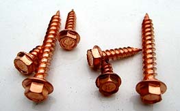
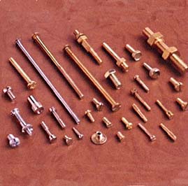
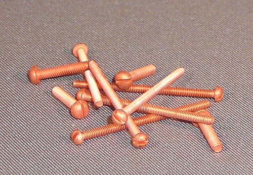
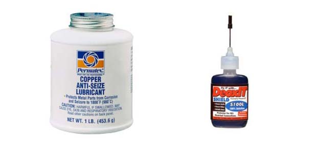
TANGENT ON FASTENERS: It is possible to upgrade all this hardware with fancy stainless steel hex-cap socket screws, AKA Allen bolts. If you really want to go all the way, find brass hardware. Brass, with its high copper content, will provide much better ground return paths and lower noise. To replace the screws that hold the bottom in place, you can use copper plated stainless steel “zip screws” that are used when installing copper guttering. For good electrical connections, and to prevent rust and seizing, use copper anti-seize on the treads (fine copper particles suspended in grease—it’s conductive!). Also, Caig Deoxit Shield (the blue) is good to use when assembling anything electrical. It can be used to protect metal-to-metal connections in fasteners and where two pieces of bare metal need a good electrical joining. Noise destroys detail and wastes power. I’ve worked in manufacturing where the grade and type of fastener is critical. The correct fasteners can make all the difference in the world; if you don’t believe me, ask anyone in aviation.
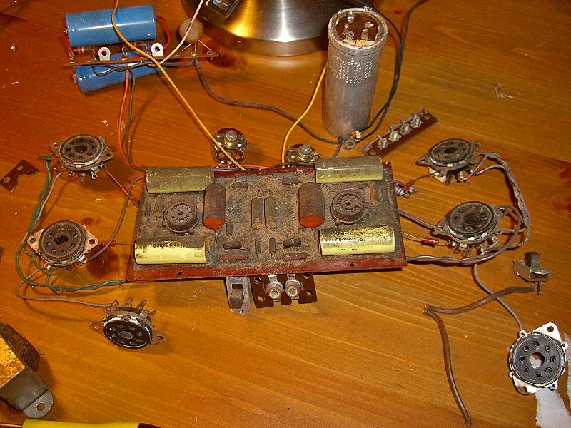
Back to the tear-down: After the transformers are removed, unscrew and remove the terminal strips (speaker connections), input jacks, power switch, stereo/mono switch, fuse holder, etc, etc. At this point, what is left should be riveted to the enclosure, unless screws were used to mount the sockets. The unit I rebuilt was a factory assembled unit and the tube sockets were riveted in place. What you will need is a drill bit that is larger than the hole in the chassis. You need to drill away the underside of the rivet. If you do it correctly, you will cut the rivet in half. For safety, wear glasses, some kind of leather or cotton gloves, and choose a drill bit that is strong. It might be tempting to use one that will go through the hole, but don’t. When it breaks through, the drill will pull itself through the hole, pulling the drill and your hand with it, crashing the drill’s chuck, and your hand, into the bottom of the chassis. I’ve received a pretty nasty cut from doing this, as well as accidentally damaging things on the blind side.
The “can cap,” the main power supply capacitor to the right of the power transformer and behind the PCB, requires some old fashioned destruction. There are little metal “ears” that are part of the outer metal jacket, that go through the chassis and are twisted to lock the capacitor in place. Many times these ears have something soldered to them. What I usually do is take a small set of pliers and just twist them back and forth until they break, then just yank the capacitor out. Old electrolytic capacitors are junk, so don’t worry about messing them up. Throw it away, and then wash your hands thoroughly. I don’t know of any nasty contaminants in these old electrolytic capacitors, but it’s better to be safe. It’s good to use gloves.
Once you have drilled out all the rivets, you should be able to pull out a wiring/socket skeleton that is somewhat amusing to look at, but best placed in the trash. Back in the “good old days,” when we had massive stray capacitances and induced hum from point-to-point wired equipment, the assemblers used a peg board to lay out the wiring, and the sockets too, presumably. I really didn’t get it until I ripped the guts out of a malfunctioning Altec 1569a. I set the wire loom to the side and finally saw that all those clean, gently radiused, right angles were made with wooden dowels. It’s so much easier to do that, then install it in the unit where room to work is at a premium.
- (Page 1 of 3)
- Next page →

What ever happened to the third or final part of the K & K Audio power amplifier?
Gary,
I’ve been stagnant with DIY while trying to get a new business up and running. I plan on sending in the final part of the story in early September.
Thank you for your interest.
Regards,
Phillip
Hi Phillip,
I have enjoyed your article which had my attention due to the fact I have been working with Kevin Carter putting together an st70 inspired amp with one or two modifications I required (240 volt and both 4& 8 ohm taps) for which Kevin will provide all the necessary hardware except the valves. This is something new for Kevin as up until now he has only provided the K&K board and shunts.
I was interested to here your third installment, especially you final listening views, and also to hear of anything which may have proved tricky – basically using you as the mine sweeper.
Please let me know how you got on and if in fact you have finished your DIY project.
Regards,
Tim.