Assembly
I’ll make this easy. If you don’t know how to read a schematic, solder and trouble-shoot, don’t do this project. It is not easy. There are umpteen chances to insert the wrong resistor, some are very difficult to read with the naked eye but I measure everything anyway, for a cold solder joint, to electrocute yourself, burn yourself, kill animals, burn down the house, etc..
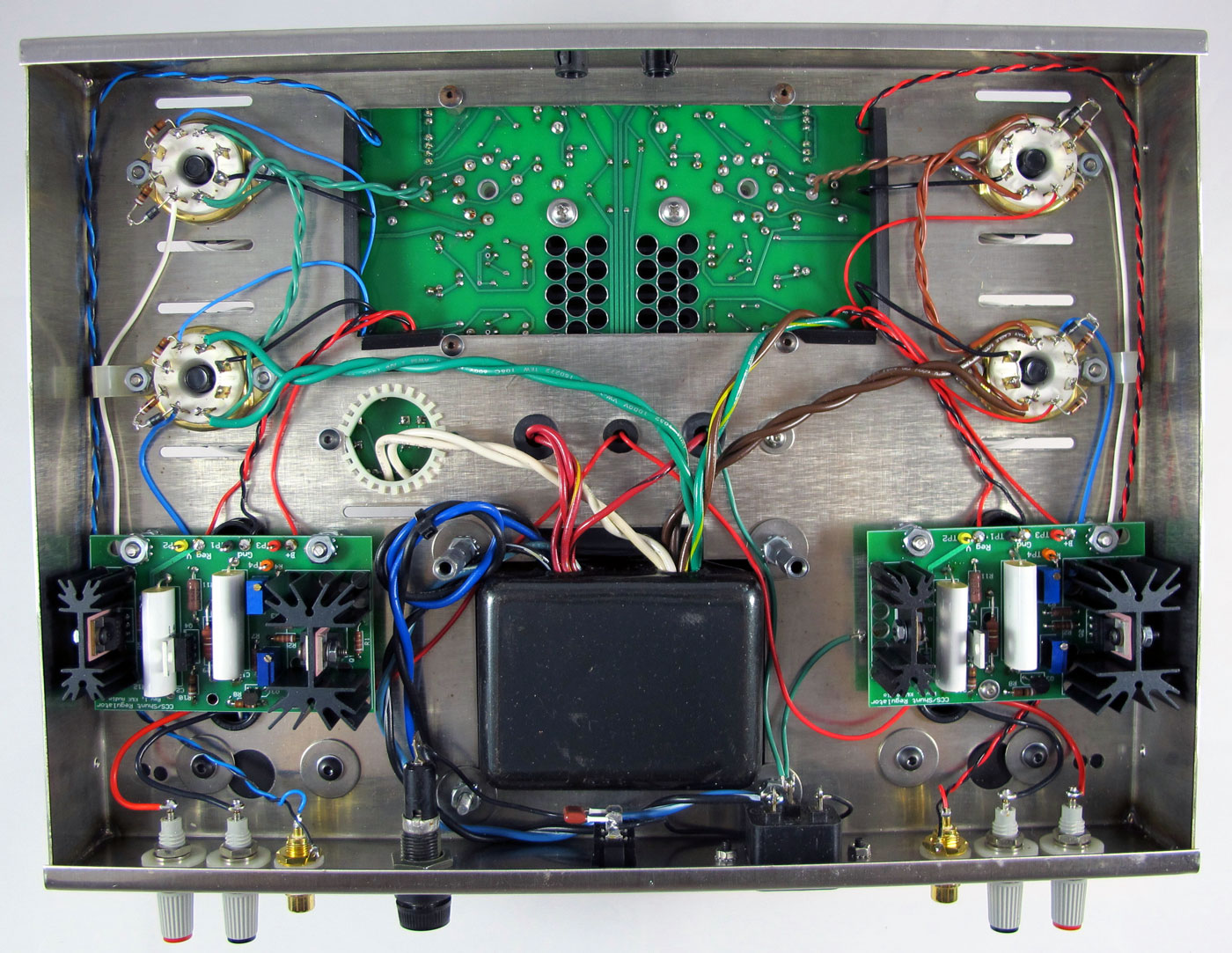
Fitting the optional regulator boards add complexity and more wiring to an already re-purposed chassis. The K&K board doesn’t perfectly fit the stock ST70 chassis, meaning that it bolts up well, but you have to run wires from the bottom of the PCB, down, inside, then around the chassis. If I do another, I will use grommets and drill small holes for the wires to feed through the chassis. It would be easier to show you a picture for you to understand what I am saying. But the thing is, you have to be careful about how you “dress” the wires, how you route the wires, so that you don’t criss-cross their connection, since you cannot see the underside of the PCB, whence the wires originate, when the amp is turned upside down. Diagram that sentence! Further, you have to prevent bare wire from touching the chassis, or another bare wire, so you cannot leave too much bare wire when inserting them into the PCB.
I always polish everything to be soldered, even the eyelets on the tube sockets, with “000 steel wool”, then measure every component with a VOM to “match pairs,” tape them to a piece of cardboard, and I use a very hot soldering iron.
Don’t use a wimpy soldering iron. A 30-watt iron puts less heat into a component than a small iron that you have to hold on the part for longer. Temperature, times the amount of time you hold the soldering tip to a component, is the total heat. The longer you hold a colder soldering iron to a part, the higher the total heat load. I’ve never once destroyed a polystyrene capacitor with a hot iron. If you do, you are doing something wrong.
Using steel wool removes oxides that prevent a good mechanical connection. Solder is not “magic electron glue.” It matters not one bit what kind of solder you use, if you have a good mechanical connection. If there is metal-to-metal contact, the solder is only there to prevent the joint from being contaminated by oxidation and intermittent. No solder is a “good conductor” compared to copper, so use the solder with the lowest melting temperature.
So, it is a good practice to “storyboard” your components after you polish the leads and measure them, then use an adequate soldering iron and a low-temperature solder. BTW, it is a good policy to measure every component, every time. Duds happen. Components are even mislabeled by factories. There is no such thing as 100%. Unless you are buying components that have been tested and selected to the same standards used by the military and Big Oil, like Z-foil resistors, never assume anything. You can save yourself a lot of heartache by “inspecting what you expect”.
The only time I got annoyed was with the Lundahl output transformers that do not come with flying-leads, and the taps aren’t numbered. Lundahl, please get a sharpie and write numbers on the transformer taps! Users shouldn’t be expected to figure out which-tap-is-which, when you can use the same Arabic numerals, spoken in Europe and Uhmerka.
Choices Choices Choices
Besides the hundreds of output tube combos you can use (tube type X manufacturer X date codes = thousands, probably), you can try other input tubes, besides the supplied 6n23p. That being said, the 6n23p-eb that I used in phono stages, like the Audible Illusions, was better than any other tube I tried in that tube family in that it has lower noise, higher plate dissipation, lower distortion, higher gain: all things that are good for phono stages. It would require changing the regulation current, probably, but you could try the hundreds of mediocre 6dj8s, or the lower distortion 6cg7 (like a 6sn7, they told us), or my favorite, the 6gu7 (like a 5687 my friend tells me, and I believe him). I asked Kevin and he hadn’t tried. It would be critical to get the current, versus plate voltage, in the sweet spot of the tube curves. I would stay away from 6N6P and 6H30, because they draw significantly more current than a 6n23p. Kevin commented that the small regulator boards, especially because they are inside the amplifier chassis where airflow is at a premium, cannot support significantly higher current. What would be the benefit of trying different input tube types? Potentially not much. Something built into this design is perfect AC symmetry between the two tubes. In theory, that wipes out most of the differences you will hear between specific brands of tubes.
The sound can be tweaked, a little, by changing the coupling caps. For not completely obvious reasons, the choice of coupling capacitor in this amplifier isn’t as crucial as a single-ended amplifier, since it is symmetrical class A push-pull, which tends to mask the sound of components.
You can also wire up the output tubes several ways. First, and most obvious for this application is triode wiring. Second, like Dynaco, you can wire them in UL. Not as desirable, for a number of reasons, is true pentode. I tried a fourth option not listed anywhere, but suggested by Blumlein in his Ultralinear patent .*
Tune Up
The process for biasing the amplifier is straight forward, if a bit awkward. The extra-huge heatsink on the PCB means you cannot simply turn the amplifier over when adjusting the small regulator boards on the underside of the chassis although this is an optional upgrade, and not everyone will have to adjust these boards. With a stock ST70, you can turn it on, and flip it upside down, carefully, to test voltages. It is a bit inconvenient to check the plate voltage for the input tubes, then turn the amp over to adjust the small potentiometers on the two regulator boards. I had the amp on its side, and the size/shape of the cases for the Lundahl output transformers makes the position awkward. I was a bit nervous while all of that was going on.
The wonderful thing about these bias adjustments is that they don’t wander up and down as the amp heats up, or the wall voltages change. The bias was extremely steady.
I recommend using a variac when turning the unit on for the first time. A variac can limit the damage from a botched job. Start off at 70 volts, or thereabout. The time-delay warm-up circuit won’t kick in until a certain threshold voltage is reached, so don’t expect the relay to kick in at ½ AC power. You’re looking, smelling and listening. Is anything going “BZZZZZZZ”, or “POP!”? Anything smell acrid? Are the parts inside the tubes glowing red? This is assuming you know nothing about tubes, or electronics, but you still put it together yourself. Every experienced builder has blown stuff up. Even with this build, I managed to short out a lead while being very careful; and knowing I was going to write about it, I still screwed up. So, it happens. And I was looking, smelling and listening. I smelled something funny, and saw some smoke, so I turned off the power. Since I have screwed up before, it took me 30 seconds to find the short.
- ← Previous page
- (Page 2 of 3)
- Next page →