Publisher’s note: Every product comes with an Owner’s Manual to familiarize the customer with its operations. These documents are often written in a dry style and to the point. But once in a while, we come across vast sections in Manual that reads like a smooth presentation of ideas and juicy description of brilliant technologies, and if we’re lucky, even a story on the challenges faced by the engineers and designers in bringing the concept to fruition. ‘Design Notes” is a new series created to feature the informative and well written documentary inside those Manuals to the readership, to offer knowledge and viewpoints that we believe will benefit and even entertain us. All materials are reprinted by permission.
Submit your Design Notes tips to publisher@dagogo.com.
Sound Lab Electrostatic Loudspeaker
“The Complete White Paper”
Thank you for your interest in Sound Lab. This paper is designed to introduce you to our technical philosophy, and it is our hope that it will answer any questions that you may have regarding our products.
Sound Lab has been in business since July 1, 1978. The founders of the company, Dr. Roger West and Dr. Dale Ream, shared a belief that electrostatic transduction was potentially the optimum technology for loudspeakers. Over the intervening years, the company has successfully addressed many major problems of electrostatic speaker technology. In addition, our initial goal was, and remains, to eliminate as much as possible anything that would detract from the purity of the reproduced sound. In particular, it has been desired to develop a loudspeaker incorporating the following attributes:
1. Truly full-range electrostatic technology having high reliability, wide dynamic range, good sensitivity and excellent bass response.
2. Single-membrane technology from which the full audio spectrum is radiated, providing perfect time-alignment.
3. Ideal phase response by eliminating the use of spatially separated multiple drivers to cover the audio spectrum.
4. Dipole topology to eliminate enclosure coloration.
5. Line-source topology to provide uniform response over the entire listening area from wall to wall and from floor to ceiling, and to reduce wave interference patterns by eliminating floor and ceiling reflections.
6. State of the art electronics employing toroidal audio transformers to preserve subtle nuances inherent in music, high-grade polypropylene foil capacitors with low dielectric absorption and high-current capability, military grade resistors, iron-core inductors, and a regulated bias supply for stable sensitivity.
7. Wide range equalization controls to provide a flat response in virtually all listening rooms.
8. Furniture grade esthetics that will grace virtually any room décor.
We feel that we have successfully satisfied our initial goals.
The electrostatic speaker art was in its infancy when Sound Lab started business back in 1978. Thus, by default Sound Lab is a research and development laboratory as well as a production facility as a result of its ambitious goals, which require that the technology base of the company necessarily continues to grow. A strong patent and trademark base has resulted from this continued effort. From the perspective of a customer, however, this could cause some uneasiness since the product they elect to purchase might possibly become obsolete if its technology is superseded. To allay this fear we have established a policy that any product that we manufacture can be brought up to the present technical level at a reasonable cost.
Our products are meticulously handcrafted piece by piece. Each operation is carefully accomplished and checked to make certain that it is correctly manufactured. Batch processing and mass production techniques could not insure the individual quality of each product that we manufacture.
The following sections provide an in-depth consideration of the technical principles upon which our products are based.
1. How Do Electrostatic Speakers Work And What Are Their Advantages?
This section describes the basics of electrostatic speaker technology. The following material is taken from an excellent article written by Jacob Turner entitled: “Why Electrostatics?” The article provides a good tutorial on electrostatic speakers and why they have decided advantages over other speaker technologies:
“Since the latter half of the nineteenth century (circa 1871) the reproduction of sound through electrostatic transducers has stirred the creative vision of professional engineers and idle dreamers alike. It is an interesting fact of history that no other single device in the audio equipment hope chest has enjoyed such an extensive and prolonged courtship between engineer and Audiophile as the electrostatic transducer.
Early attempts to embody this means of sound reproduction were only marginally successful partially because of the lack of suitable materials and processes.
What is the glamour of the electrostatic principle that gained it such extended, devoted attention? Why has the electrostatic transducer remained the standard of excellence by which other acoustic devices are so often measured?
The answer to these questions lies in at least three areas, which will be discussed in the following order:
1. Some peculiarities of the hearing process
2. The nature of the acoustic medium: air
3. The operational features of electrostatic acoustic devices as related to the above and to dynamic acoustic transducers
The recent increase of activity in the highly elusive area of psycho-acoustics promises to contribute significantly to a more profound grasp of the complexities of man’s perception of his sound environment. Several recent studies have been carried out concerning the sensitivity of normal adults’ ears to different levels of harmonic distortion. The results suggest that relatively high levels of harmonic distortion (odd and even order) are imperceptible in the presence of normal musical program, while quite small changes in amplitude and phasing are readily ascertained. Amplitude changes were described as altering the tonal quality of the program, while phase displacement e.g. bass and treble of no more than 5 degrees degraded the clarity and definition of musical transients and upset the homogeneity of the stereo image between two major frequency bands.
Other studies have pointed out that the inherent transient nature of musical and speech sounds dictates a high level of transient fidelity as a prerequisite of high quality acoustical transducers. The significance of these observations insofar as electrostatic transducers are concerned will be pursued a little later.
Another vital link in the chain is air, which has the following major characteristics of behavior that are germane to our topic. Air is highly compressible, that is, the amount of air pressure (number of air molecules) in a given space can be increased or decreased beyond its normal condition. Air, then, can be said to be like a spring, a means for storing energy; a compliance. Air also has weight or mass. Ten pounds of air are just as heavy as ten pounds of potatoes. Air is, therefore, like an inertance, which opposes an action or force; an inductance. Air can also be randomly excited, air molecules consume power by generating heat. Air can then be said to be like a resistance. This acoustic impedance is normally very low, although at high audio frequencies it is considerably greater than at low audio frequencies. In order to insure that the transfer of diaphragm or cone motion to air motion occurs with the greatest efficiency, it is necessary that the total mechanical impedance of the device be as close to the acoustic impedance of the body of air it is exciting over as much of the audio range as possible.
To relate the preceding discussion to the topic of the electrostatic transducer, it will be necessary to outline the operational features of the push-pull electrostatic device. The previous points will be related at the same time to the operational features of the dynamic transducer. As illustrated in Fig. 1, the electrostatic transducer is composed of a thin membrane (diaphragm) made of Mylar that is stretched and contained between two acoustically open plates. The two plates are connected to either end of a coupling transformer which provides the high voltage audio signal. The diaphragm is connected to a high voltage, low current bias supply, which provides an electrostatic charge that becomes trapped in the diaphragm.
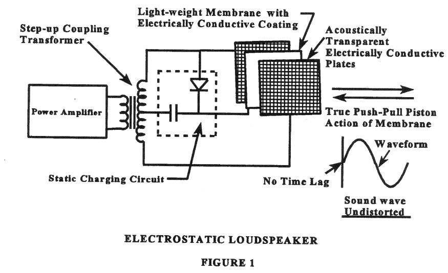
In recent years a method called “electretification” has been developed whereby the bias charge is permanently embedded in the diaphragm material, so that the diaphragm is self-energized without an external source of bias voltage. The net result is the same in both cases. The two plates provide an electric field that is the voltage equivalent of the audio signal. In the presence of an audio signal, the electric field exerts forces on the electrostatic charge that is trapped in the diaphragm. These forces are transferred to the diaphragm, causing the diaphragm to move in synchronization with these forces.
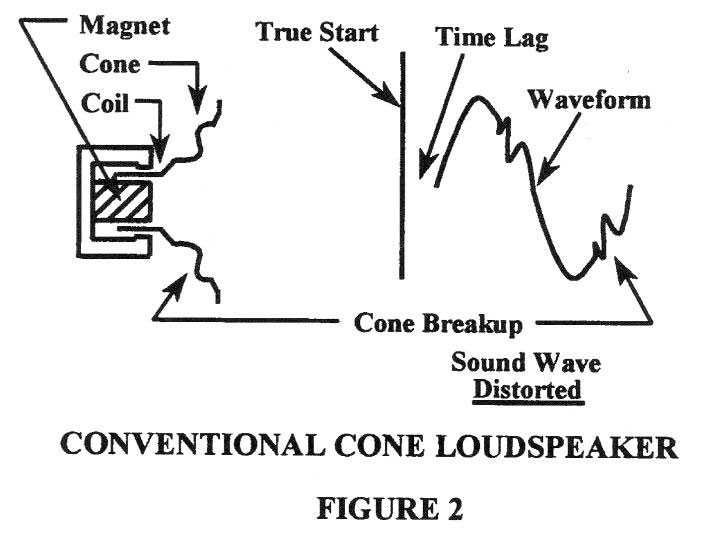
By contrast, Fig. 2 will illustrate the make-up of a dynamic driver, which consists of a frame housing, a magnet, and a voice coil attached to the apex of a cone which is suspended at its edge by a flexible cloth or other material. The voice coil is set into motion in synchronization with an audio signal that causes current flow through the coil. As the coil is set into motion by this signal, it in turn sets the cone into motion.
Although both units achieve air excitation through diaphragm or cone motion, the manner in which this is done involves radically different techniques and results. The electrostatic device employs the use of a moving member for all its operating frequencies that is usually only 0.0004 inches thick (Note: the material used in Sound Lab speakers is only 0.00012 inches thick) and weighs only as much as a body of air 7mm thick (2mm thick in Sound Lab speakers) whose boundaries are equal to those of the moving diaphragm.
The electric field, which acts to make the diaphragm move, exerts its actuating force uniformly over essentially the entire area of the diaphragm. A diaphragm of such extreme lightness, in combination with an actuating force that is uniformly distributed over the entire surface of the diaphragm, results in a transducer whose transient response closely duplicates the electrical input. The net result is a diaphragm motion that is a very good replica of the electrical forces acting upon it, with all sections of the diaphragm surface moving with highly accurate phase and amplitude linearity throughout its entire range of travel, at all frequencies within its area of operation.
The forces acting to move the dynamic transducer’s cone, however, produce different results. The application of the driving force only to the apex of the cone necessitates a sufficiently stiff cone to prevent buckling and deformation of the cone structure. Such a stiff cone normally has considerable mass, which degrades its efficiency, its transient response capabilities, and its high frequency performance. In addition, the forces applied at the apex do not act uniformly over the surface of the cone, causing the cone to “break-up” into an infinite variety of vibrational modes, only one of which is truly representative of the original signal. This mode of operation produces amplitude and phase nonlinearity often of considerable magnitude, and these tend to increase as the cone is driven to greater excursions. Obviously, the discussion of dynamic driver operation relates quite strongly to the previous discussion concerning the unusual sensitivity of the human ear to the problems of transient response, amplitude linearity, and phase linearity. The basic conclusion is that an electrostatic unit behaves with better composure in all of the above areas.
The second major distinction involving electrostatic transducers deals with the considerable problem of coupling to the air with reasonable efficiency over the entire audio band. The electrostatic unit, because of its extremely low mass diaphragm and the uniform distribution of’ the driving forces over the entire diaphragm surface, is inherently a unit with low mechanical impedance at all frequencies. As such, the coupling problem at low frequencies (where the problem is greatest) for electrostatic units is considerably less than for dynamic units, which are encumbered by a high mechanical impedance. The result of these conditions is that the electrostatic unit performs quite well down to its frequency limits and within its maximum excursibility with equal fidelity at all drive levels.
The dynamic cone unit, because of its poorer coupling, must be driven harder to produce satisfactory excitation of the air at low frequencies, and usually encounters a number of problems involving cone break-up, non-linear motion of the voice coil due to loss of magnetic coupling in the gap, suspension non-linearities, etc. In all fairness, it must be said that the performance level of today’s popular dynamic acoustic transducer is incredibly good given the economic and operational constraints of that type of unit. On the other hand, the superiority of the electrostatic principle has been demonstrated by the great acceptance of the increasing number of electrostatic headphones which have already emerged in the market. In addition, of course, several electrostatic speaker products are highly regarded by the audiophile community.”
We greatly appreciate Jacob Turner’s ability to explain the advantages of electrostatic technology over conventional dynamic (magnetic) technology. We would add that the comments regarding cone speakers apply to ribbon and other types of speakers also. In the case of ribbon speakers, they are planar in nature but the percentage of the area of the diaphragm that is directly driven is on the order of 30% to 50% instead of 100% as in the case of electrostatic speakers since the driving force comes from a thin piece of wire or foil that represents only a fraction of the total moving area. Thus, as in the case of the cone speaker, a significant portion of the diaphragm is not directly driven and can inherit some of the drawbacks of cones. Furthermore, the wire or ribbon is usually sandwiched between two plastic films which adds to the moving mass. In general, the ribbon speaker is better than its cone counterpart in terms of motional accuracy, but it has upwards of ten times the moving mass of a properly designed electrostatic speaker.
2. What Is The Relationship Between Speakers And Microphones And How Is It Optimized?
The goal of high-end audio is to recreate a sonic performance with as much accuracy and realism as possible. This demands near-perfect performance from every component in the reproduction system, including the characteristics of the sound room. But it also requires a compatibility with certain circumstances involved in the recording process which have to do with the accuracy of the recreated stage (stereo image, both size and location), ie: the spatial aspect of the re-creation. Perhaps, the more important of these has to do with the characteristics of the microphone(s) used to record the performance and their placement.
Not much can be done to compensate for signal timing corruption due to mix-down procedures and bizarre microphone techniques. These are in the hands of the recording engineer. But, something can be done concerning an acoustical principle that we refer to as microphone/speaker reciprocity. In the early days of stereophonic recording it was generally accepted that the “standard” microphone arrangement was to place two microphones facing the orchestra which were separated by eight feet. Reciprocally, the loudspeakers reproducing the recording would also be separated by eight feet. There have been many alterations to this simple geometry since then, such as employing more than two microphones to obtain special effects and sonic highlighting. However, amid the rather complex science of recording, one generality persists. Most microphones used in recording employ a cardioid (directional) pattern. A microphone having this characteristic readily accepts information from the front but attenuates sound waves approaching from the rear. Considering available units, the limits of the cardioid acceptance pattern is such that pickup sensitivity is diminished by 6dB (half pressure) varies from about 30 to 45 degrees either side of the central axis of the microphone.
The principle of reciprocity simply states that in order to recreate a sound stage with good spatial accuracy, the dispersion angle of the loudspeaker and the acceptance angle of the microphone should be similar. For example, were you to walk around your sound room and compare the recreated sound field to walking around the auditorium during the actual performance, similarity of the stage image can only be achieved if the principle of reciprocity is implemented. For this reason all Sound Lab speakers are carefully designed to fulfill this important principle. More about the requirements for accurate staging will be discussed in a later section.
Another advantage that is accrued from a wider dispersion angle is that harsh direct reflections from walls are greatly reduced, making speaker setup much easier since undesirable room modes tend to be less pronounced. Through experience we have found that horizontal dispersion angles from 45° to 90° work well in the home environment. The more narrow angle provides greater speaker sensitivity and dynamic range while the wider angle provides a wider stage. Both angles are available in our products.
3. Sound Lab Speakers Don’t Seem To Sound Any Louder Up Close Than They Do Far Away! How Is This Done?
The secret behind this seemingly magical trait has to do with the characteristics of the acoustical line source. All Sound Lab products are categorically vertical acoustical line sources. My opinion is that the vertical line source is the optimum acoustical geometry for proper staging and acoustical energy control in the home listening environment, which I will now attempt to justify.
Theoretically speaking, a vertical acoustic line source is a two-dimensional vertical line, having infinite length and zero diameter, from which full-spectrum sound energy emanates. It might be helpful to envision a long violin string, sufficiently long in order to produce lower frequencies. In the real world, where an infinitely long line is an abstraction, the length of this line needs to be large compared to the all wave lengths that it radiates (there is an important exception when used in an enclosed room, as will be discussed later). If this criterion is met, the major characteristic of the vertical line source is that it disperses energy only in the horizontal direction and none in the vertical direction. In other words, all sound rays emanate perpendicularly from a vertical line. Therefore, the radiation field might be compared to the shape of a slice of pie in which the top and bottom surfaces are flat (no vertical radiation) and side radiation is confined to a prescribed angle (horizontal dispersion). In contrast, most speakers available on the market are more related to the “point source”, the characteristic of which is a uniform radiation pattern in all directions: up, down and sideways.
My justification of why I believe the line source to be superior to the point source in the home environment will now be considered. For those who don’t wish to get entangled in mathematics I will first give an explanation that appeals to the intuition. This will be followed by a more rigorous approach.
In your mind’s eye, envision an infinitely long vertical line from which perpendicular energy rays are being radiated. A bottle brush held vertically would be a good analogy wherein the spine is vertical and the bristles radiate horizontally. It should be intuitively clear that If a thin flat surface, that’s parallel to the energy rays, is placed on the line, it would not disturb the rays since there would be no reflections. Now, place a second flat surface, parallel to and above the first surface. Neither of the surfaces will interfere with the energy rays. In other words, the pattern of the rays between the plates would not be affected by the presence of the plates. Consider that the lower and upper plates represent the floor and ceiling of a listening room. The point being made is that if a line-source speaker is placed in a room, the sound it emits will preserve the characteristics of an infinitely long line source. One might ask what the benefits of this might be. First off, it eliminates floor and ceiling reflections, since all sound rays are parallel with the floor and ceiling. The consequence of this is that the complexity of interference waves within the room is minimized, providing a more pure sound field. The horizontal dispersion of the speakers is designed to minimize wall reflections. Secondly, since the line source has no vertical dispersion, all energy is concentrated in the horizontal direction. The theoretical effect of this, ignoring the reflective field resulting from wall reflections, is that sound drops off at only 3dB per doubling of distance from the speaker rather than 6dB per doubling of distance as in the case of the point source. Therefore, as the listener walks toward or away from a line source, changes in loudness are much less apparent. That is why the sound level of our speakers does not seem to drop as one walks away from them, nor does it appear to become louder as one approaches them. Thus, the sound level does not vary noticeably as one moves toward or away the speakers, which makes the entire room the proverbial “sweet spot”.
One might wonder how a large speaker could possibly function as a thin vertical line source. As pragmatic proof, simply walk around to the rear of one of our speakers while it is reproducing sound. Using an ear as a detector, a dramatic increase in sound level will be apparent at the center of curvature of the speaker. The sound rays emanating from the horizontally curved radiating surface will converge at a point about three feet behind the speaker, and beyond this point the rays will diverge. This focal point is the virtual line source. Thus, as incredible as it may seem, the sound from our huge speakers appears as if it is being radiated from a minuscule vibrating vertical line. The more near the top of the speaker is to the ceiling, the more accurately it performs as an infinite line source.
The only requirement for a truncated vertical line source (being trapped between a floor and a ceiling) to perform as if it’s an infinite line source, is for the floor and ceiling be acoustically reflective. It can be shown mathematically that the interaction between the floor and ceiling reflections create infinite phantom extensions of the line source above and below the room. It works in this manner, the vertical component of any ceiling reflection will be cancelled by a complementary reflection from the floor (and vice versa) leaving only the horizontal component. In the real world the floor and ceiling will absorb some sound energy, but the effect is not sufficient to alter the line characteristics enough to be audible. The net result is that the listener can sit down, stand up, do deep-knee bends, walk back and forth and the sound image does not appear to change. A point source cannot give this type of performance.
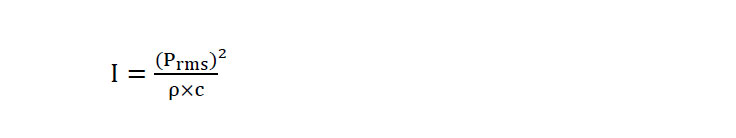
To make this more meaningful, I shall be somewhat rigorous mathematically. The acoustic intensity (I) of a sound wave is defined as the average power transmitted per unit area in the direction of wave propagation:
Where:
I = average power transmitted per unit area in the direction of wave propagation
Prms = effective pressure in nt/m2 (newtons/square meter)
c = velocity of sound in m/sec (meters per second)
ρ = density of air in k/m2 (kilograms per square meter)
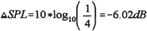
With the point source, the area that energy is distributed over is quadrupled each time the distance from the source is doubled. Thus, in decibels, the intensity of a sound drops approximately 6.02dB for each doubling of distance:
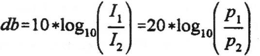
Since doubling distance reduces (I) by a factor of four:
In comparison, with the line source area, the sound level changes only by a factor of two for doubling the distance toward the line source, since doubling the distance distributes the sound energy over only twice the area. Thus, doubling the distance from a line source reduces the sound level by only 3.01 dB. In other words, sound intensity drops off with increasing distance significantly slower with the line source than with the point source.
For the mathematically inclined, a more rigorous treatment of the line source will now be given. To begin with, when comparing standard sensitivity measurements of point sources versus line sources, it is common to misinterpret the results as it applies to sound pressure levels at standard measurement distances. The reason for this controversy is due to the proximity effect of the line source compared to that of the point source. Sound level varies as the inverse of distance for the line source, whereas it varies as the inverse of the square of the distance for the point source.
As a result of the difference in proximity characteristics, comparing the standard sensitivity measurement values of the line source and point source (normally measured at one meter with one watt of input power into 8 ohms) to the sound pressure level measured at normal listening distances, the result can be startling. Generally, the point source speaker has a higher energy density at the standard one-meter distance than that of the line source due to the energy of the point source being concentrated into a smaller area compared to the line source, and thus typically has a higher standard sensitivity rating than that of the line source. However, when the sound level is measured at a typical listening distance from the speaker, say 25 feet, this distance compared to the standard 1 meter distance is about eight times greater, giving the line source nearly a 9 dB advantage over the point source. Since this advantage increases with distance, there comes a point, we term as the “critical distance” where the sound pressure level (SPL) of the line source equals that of the point source. Beyond this point, the line source continues to increase in loudness at a +3dB/(doubling of distance) rate compared to the point source, as distance is further increased.
Thus, when standard one meter sensitivity measurements of a line source and a point source are compared the results can be deceiving. It only makes sense to measure sensitivity at the listening distance rather than at one meter when comparing point-source and line-source speaker sensitivities.
Perhaps, the best way to relate standard one-meter sensitivity values with the performance at typical listening distances is to calculate the distance from the speaker at which the sound level is the same as a function of the difference of the one-meter sensitivity ratings of the two speakers. Keeping in mind that the line source SPL drops off at a slower rate than that of the point source and further, that the one-meter sensitivity rating of the point source is typically greater than that of the line source, there is inevitably a distance from the source where the sound level will be the same, beyond which the line source will always be louder than the point source. In fact, the degree that the line source is louder than the point source is proportional to this distance.
The formula for this critical distance (D), where the line source and point source have the same SPL, is given by:

Where:
D = the distance in feet where the point-source and the line source have equal SPL
RP = Rate of change of a point source SPL as a function of doubling distance: -6dB/octave
RL = Rate of change of a line source SPL as a function of doubling distance: -3dB/octave
SP = One-meter sensitivity of a point-source speaker: SPL in dB @ 1 meter
SL = One-meter sensitivity of a line-source speaker: SPL in dB @ 1 meter
SP and SL are obtained using the standard method of measuring speaker sensitivity. This equation assumes that the point-source speaker sensitivity (SP) is greater than that of the line-source speaker near the speakers, which is a safe assumption in most cases.
This equation is derived from the fact that the theoretical infinite line-source obtains a 3.01 dB advantage over the theoretical point source with each doubling of distance from the source in an anechoic environment. In practice, actual speakers will differ from the theoretical model by varying degrees depending on how closely they emulate either a point or a line source, hence one might expect that the results may vary somewhat from the ideal case. Notwithstanding a departure from the ideal, the principle holds true and can be quite significant.
A remarkably accurate simple rule-of-thumb is:
“The critical distance D (in feet) is approximately equal (within 10%) of the difference between the one-meter sensitivity ratings (in decibels) of the point-source and the line-source.”
That is: D ≅ SP – SL (within 10% accuracy)
For example, our Model Majestic 745 speaker has a one-meter sensitivity rating of 89 dB. Let’s compare that to a hypothetical “Brand X” point-source speaker having a higher sensitivity rating of 96 dB. The critical distance calculates to be 7.63 feet (the rule-of-thumb gives 7 feet). Beyond this distance, the Majestic 745 will be louder for the same input voltage (this calculation assumes an anechoic environment). Acoustical environments that are only partially absorptive, such as the average home listening room, will cause some variation in actual measurements, but the general principle still applies. The moral to the story is:
“To properly compare the sensitivities of line-source versus point-source speakers, measurements should be taken at normal listening distances rather than at the standard 1 meter.”
Now, from a pragmatic viewpoint, let’s interpret the above conclusions in terms of advantages in the listening room. First, consider the effects on the perceived sound field caused by walking to-and-fro in front of a live orchestra in a symphony hall. As one stands near a side wall, the more near musical instruments appear louder than the ones further away, but they will not mask (override) them. As one walks to the other side of the hall, a similar effect is obtained. In other words, the acoustical sound stage is skewed as one stands to the side, but a three-dimensional image of the entire orchestra remains. This is exactly the effect of listening to music reproduced through stereophonic vertical line sources. More specifically, as a listener walks to one side of the listening room, the speaker nearest him does not become significantly louder and, hence, does not mask the sound of the other speaker. In fact, as the listener moves around the listening room the spatial image of the reproduced orchestra responds very similarly to that of an actual orchestra playing in a music hall. In contrast, the point-source speaker becomes significantly louder as one approaches it, and is thus capable of masking the sound of the more distant speaker. Therefore, one must remain equidistant from the two speakers to obtain accurate staging.
The line source has further advantages. As mentioned previously, sound rays emanating from a line source radiate perpendicularly from the line. Thus, the sound that reaches the ear comes from sound rays that are at the same level as the ear. Therefore, as the listener stands or sits the sound is the same. Thus, one never listens “up to” or “down to” the sound source. The point-source, to the contrary, has a very distinct vertical position that can be easily localized, which may give music an artificial vertical localization effect. Contrary to some common beliefs, stereophonic music does not contain any vertical localization cues and, therefore, a true vertical image does not exist. To create a true vertical image it would require an upper and a lower set of speakers (with the corresponding four-channel microphone/recording setup with which to make such a recording) to simultaneously reproduce the vertical and horizontal images. Thus, the line-source speaker does not create artificial vertical localization such as multiple driver point-source speakers can do.
4. How Does Sound Lab Achieve Profound Bass Response With Dipole Panel Speakers?
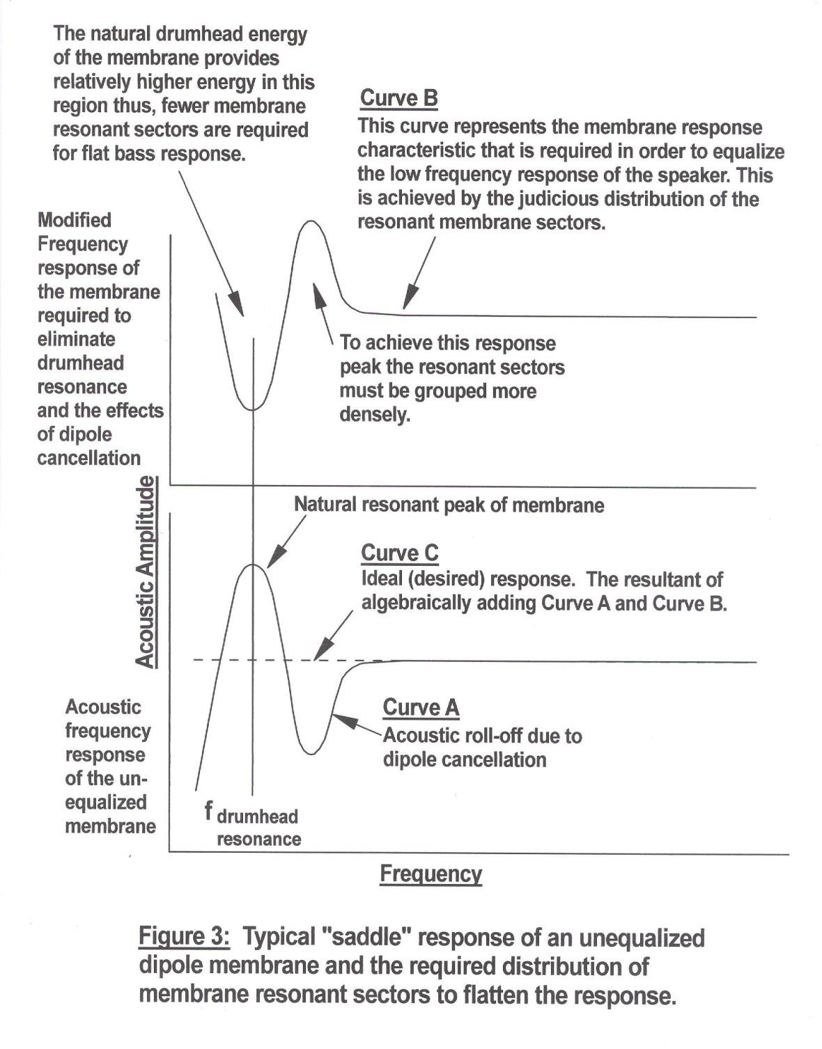
If a compliant material, such as a drumhead, is stretched over a frame and the drumhead is tapped with a mallet it will produce a sound having a distinct frequency, which is referred to as the drumhead resonance. It requires less energy to cause the membrane to vibrate at this frequency than any other frequency. Thus, if a vibrator is coupled to the drumhead and the frequency of vibration is varied, when the drumhead frequency is approached the vibration of the membrane will become much greater than at other frequencies. This is the case with the electrostatic speaker as well, since a membrane is similarly stretched over a frame. As with the drumhead, the membrane of an electrostatic speaker will exhibit a strong resonant sound with relatively low input energy. This is a problem since when the audio signal hits the resonant frequency the membrane will amplify that particular frequency more so than all others. If not tamed, the resonant energy will create a coloration to the sound. Furthermore, since the membrane vibrates greater at resonance for a given input signal level, the membrane can easily be driven into the stators, which limits the usable dynamic range of the speaker. This resonant peak can be 20dB or higher and usually occurs at the lowest frequency of the membrane’s pass band.
Various methods have been employed to eliminate this resonance. Some designers have used acoustical damping, such as stretching a fine mesh, similar to that used in nylon stockings, across the speaker. This approach indeed damps the resonance, but it also reduces membrane movement at other frequencies to a lesser degree, decreasing the vitality of the sound. Other approaches have been used to eliminate this nasty peak of energy, but all have exhibited negative side effects.
It would not be surprising if we were asked how we eliminate the membrane’s drumhead resonance. An ancient philosopher once stated: “Asking the proper question leads to the answer”. Applying this wisdom, we asked ourselves: “Instead of permitting the entire diaphragm to contribute to one resonant peak, why not set up a situation where different sections of the diaphragm resonate at different frequencies in a graded fashion, which would break up the drumhead resonance into a series of manageable resonances? The resulting set of resonant frequencies could be distributed over the pass band of lower frequencies and would have no effect on higher frequencies. And, by judiciously selecting the individual frequencies the bass response of the speaker could be equalized”. We tried it. Two wonderful results were realized: the “drum-head” resonance was eliminated and the efficiency of lower frequencies was dramatically increased since all was functioning on very responsive resonant energy. The resulting bass response was flat, fast, dynamic and unrestrained. As it turns out, the “nasty” membrane drumhead resonance is a free source of energy that can be distributed to equalize the bass response of the speaker.
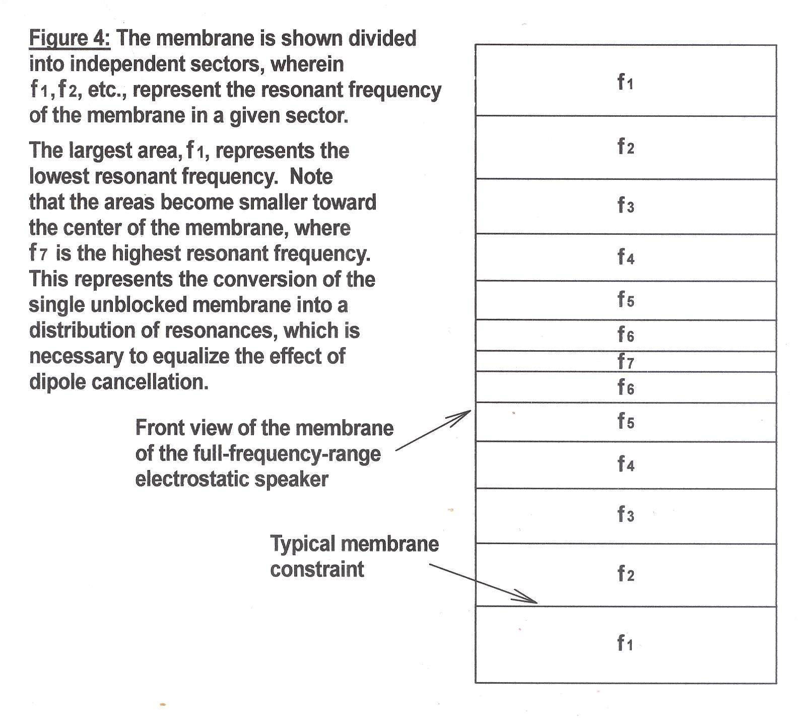
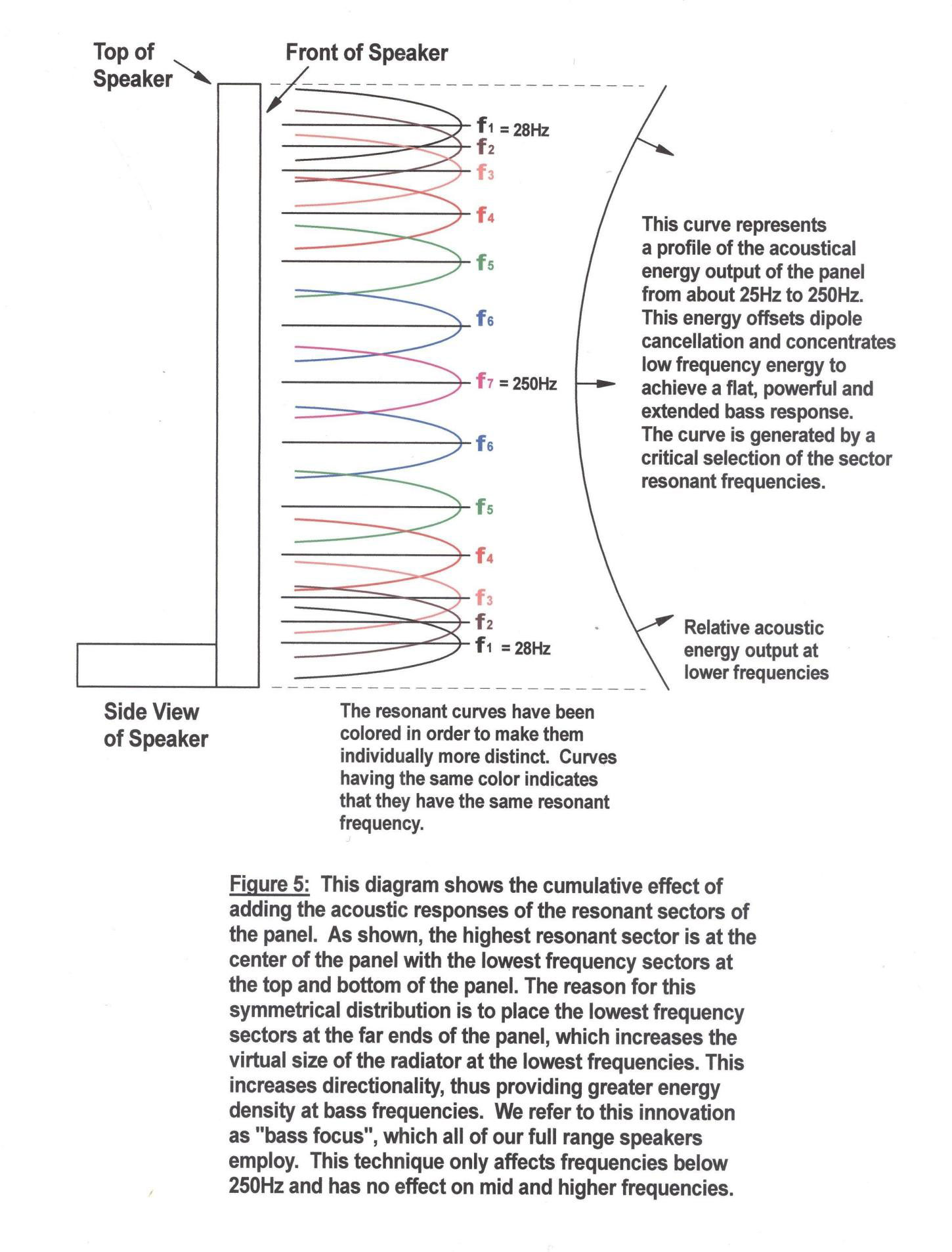
The distributed resonance principle also solves a nasty problem associated with dipole radiators: dipole cancellation. An acoustic dipole radiator is basically a vibrating membrane in which the acoustic energy emanating from both of its sides is permitted to radiate freely. Dipole radiation has vanishing acoustic “coloration” since it is devoid of enclosure resonances. However, since the two waves radiating from opposite sides of the diaphragm are mutually out of phase, they begin to cancel one another at lower frequencies, which results in a prematurely rolled-off bass response, usually occurring just above drumhead resonance. By judiciously selecting the “law” by which the resonant energy sectors are distributed, the effects of dipole cancellation can be virtually eliminated. Figure 3 shows the typical response of an unequalized dipole radiator taken axially to one side. Figure 4 shows one of several methods of sectoring a membrane to distribute resonant energy. fl, f2, etc., represent the resonant frequencies of each of the sectors. Figure 5 shows how the bass equalizing response contour is generated by dividing the membrane into a distribution of resonant sectors.
It should be readily apparent from studying these figures that the lowest frequency sectors are placed at the extreme ends (top and bottom) of the panel. This causes the apparent size of the radiator to appear equal to the height of the speaker. The consequence of this is to reduce the vertical dispersion of lower frequency energy (ie: higher directivity), thus increasing energy density. In audio terms, this represents an increase in bass dynamics. We refer to this as our “Bass-Focus” technology. This is similar to the work of Joseph D’Apolito, who employed this principle with dynamic speakers.
In the “near-field” (that is, when one is very close to the speaker) the bass response of the speaker has a rising effect as frequency is lowered. This occurs because up close to the speaker the effects of dipole cancellation are not as apparent. However, in the far-field (meaning normal listening distances and beyond) the rising characteristic seen at the “near-field” disappears and due to resonant energy distribution just the right amount of energy is supplied at each frequency to supply the energy lost due to dipole cancellation.
The resulting frequency response is flat and extended. In other words, the “law” of the distribution of frequencies is such that it provides the complement of the membrane’s unaltered natural frequency response curve. Obviously, an electronic equalizer could be used to obtain the same effect, but it would reduce the effective dynamic range of a given amplifier by 15 dB or more. By using “distributed-resonance equalization” the dynamic range of the amplifier is not compromised. This is how the nasty drumhead resonance energy is put to good use. This is about as close as one can come to “having your cake while eating it”.
5. The Electron: The Backbone of the Electrostatic Speaker:
In a conventional (dynamic) loudspeaker magnets are used to create a force field. Electrical charge is employed to do the same in the case of the electrostatic speaker. The quality of the performance of the electrostatic speaker is directly associated with how dense and how uniformly the charge field is distributed upon the membrane. Sound Lab employs a pure copper charge diffusion ring around the outer boundary of the membrane to feed charge into the center of the membrane from all directions. The low impedance of this ring insures that leakage paths, caused by such things as moisture condensing onto the membrane from humidity, has no effect on the performance of the speaker. The charge on the membrane is thus exceptionally uniform and dense. The membrane surface must be electrically conductive to permit the charge to migrate, but the resistivity of the conduction must not be too high nor too low, and it must not burn off or deteriorate with time. Such is the conductive membrane surface of Sound Lab’s speakers.
Furthermore, since the charge is fed from all points around the periphery of the membrane, the speaker “charges up” quickly. Therefore, the speaker can be disconnected from the mains if desired without requiring time to recharge when it is desired to listen to them.
6. Geometrical and Construction Considerations:
The high performance capability of our speakers has much to do with the internal geometry of the electrostatic panels. First, the spacing between the stators and the membrane is extremely critical in order to obtain the proper electrostatic field intensity plus having adequate room for the membrane to move. Furthermore, the spacing must be exactly the same for both the front and back stators in order to have optimum push-pull action and low distortion.
The framework of the panel is also critical. The whole purpose of the framework is to maintain the proper geometrical relationship between the stators and the membrane. It must be very rigid, accurately constructed and non-resonant. Furthermore, the material used must be moisture resistant and not degrade with time and environmental conditions. We therefore fabricate the internal members of the structure from a plastic that is very strong, dense, non-resonant, non-hygroscopic and immune to environmental factors. Thus, the integrity of the panel is preserved under all reasonable conditions.
The greatest general criticism of electrostatic speakers has been that they easily “arc over” and are thereby damaged. Some early design attempts have resulted in panels that break down easily which has created a bad name for electrostatics. Understandably, this could cause people to shy away from them. Sound Lab engineers have virtually eliminated this issue by employing state-of-the-art cross-linked insulating material. It is extremely rare for a Sound Lab speaker to experience a voltage breakdown, even under extreme overload. This eliminates the greatest concern of those who prefer electrostatic sound. To insure the integrity of the speakers we manufacture, each panel is tested at the maximum rated power before it is shipped.
One more important geometrical consideration should be mentioned. Some designers have attempted to provide horizontal dispersion of sound energy by using a curved geometry, wherein the membrane is suspended such that it assumes a truly curved surface. It is intuitively obvious that such a shape provides a non-symmetrical transduction characteristic, since the membrane tension increases as the membrane expands outwards and it loses tension as it moves inwards. This unsymmetrical characteristic creates severe mechanical limitations and thus prevents the speaker from performing as a truly full-range speaker. In fact, for a given membrane width, as the radius of curvature is increased the severity of the problem increases proportionately for a given membrane displacement. For this reason the horizontal dispersion angle of a truly curved membrane must be limited to a rather small angle.
In contrast, Sound Lab employs a piecewise approximation of a curved surface using flat surfaces (facets). The flat surface provides a symmetrical characteristic that permits large linear displacements. Therefore, the flat membrane approach is the only way a truly full-range membrane speaker can be realized. By judiciously selecting the proper angle between adjacent flat facets, the dispersion of the sound field can be as smooth as the curved membrane but without the severe displacement restrictions of the curved membrane. Another benefit is that there is no limit to the amount of horizontal dispersion that can be used since the membrane dynamics are not affected by the angle of dispersion as is the case of a curved membrane. Speakers have been manufactured having up to 360 degrees of horizontal dispersion, but we use an angle in our speakers that we have found to be the best angle for average listing rooms. We offer 90 degree dispersion panels for wide rooms in order for the sound to encompass the room, and 45 degree dispersion for more narrow rooms to minimize side-wall reflections. We will custom build panels for other angles upon request, up to 360 degrees.
The membrane is another critical part of the speaker panel that should be mentioned. Low mass and resistance to environmental factors are critical requirements. Sound Lab uses a polyester material that is only 120 millionths of an inch thick, which provides the high compliance necessary for large, linear membrane excursions. Also, the moving mass is so low that it represents only a fraction of the mass of the air volume it moves. Furthermore, Sound Lab uses a unique mechanical/adhesive system to insure that the membrane never slips and loses its proper tension. Finally, the membrane is coated with an extremely thin proprietary substance to give it exactly the correct electrical conductivity. This coating is virtually indestructible and will not vaporize when the speaker is played loudly.
7. Final Remarks
Sound Lab offers fifteen models, all of which employ the technologies explained in this paper. Why so many models? We offer three styles, the Ultimate series with its steel space-age frame, the Audiophile series with its gorgeous wrap-around furniture-grade wood frame, and the Majestic series having a more simple modern touch with furniture-grade wood trim.
Five panel sizes are available for each of the above mentioned styles. The sizes range from our recently introduced compact series, standing only fifty inches tall, to our largest panels standing at a monumental nine feet height. In other words, there is a size to meet all installations. The panels used on all models of a given size are identical. Further, the identical electronics are employed on all models. As a result, there are no options to be offered other than panel size and style. Our electrostatic sub-woofers and our hybrid models have not been considered in this paper in order to fully focus on our truly full-range electrostatic speakers. We invite you to contact us if you would like to know more about these.
Congratulations! It understandably requires a bit of effort to work through the details of this paper. Much more could be presented to explore our technology in more detail, but the real test is in the sound. We are proud of our technology, and we feel that our speakers are based on the most important acoustical principles that apply to sound reproduction in the home. If this presentation has not answered all of your questions, we invite you to contact us for the answers. We also welcome any suggestions that you may have.
Sound Lab Electrostatic Loudspeakers
P.O. Box 409, Gunnison, Utah 84634 USA Ph. 435-528-7218
www.soundlab-speakers.com soundlab@burgoyne.com
- (Page 1 of 1)