Editor’s Note: This article continues the discussion from Part 1. Enjoy!
15. The literature describes, “…a second response that exists well below the -3dB down corner frequency. This seems to be the measurable response which is being called the Articulation Response. It appears to be well below 1 kHz. So, would it be accurate to suggest that this is predominantly a bass/mid-bass treatment of the signal? Is the attempt to clean up the lower end the means by which the frequencies above 1,000 Hz are perceptually clearer?
I believe what you are referencing Doug is the fact that we are discussing two measurable responses. The first is what is called the Frequency Response. The second, which operates well below the frequency response is the one that MIT calls the Articulation Response. As indicated earlier, this response is measured by MIT from a fractional Hertz up to around 150 kHz.
Personally, when designing the Articulation Networks I don’t consider any audible frequency more important than another one. However, what I do pay very close attention to is making sure each frequency articulates as well as the next one.
16. What would you say to someone who insisted that MIT cables cannot yield higher articulation due to the presence of additional networking in the cables?
Then they have either not read our technical and white papers, or listened to our cables! MIT cables sound different than ‘Just Wire’, and the reason for that is because of the unique technologies found only in MIT products. Supporting those technologies are multiple patents as well as technical and white papers that can be downloaded and read by everyone.
Now, with all of that said, I understand we all hear a little differently, and I can’t account for someone’s personal preferences.
17. Have you conducted tests to determine if achievement of the articulation might be better served via implementation on the speaker cables versus the interconnects? If so, what was the result?
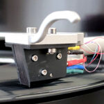
Very honestly, I believe that both are needed. The system is only as good as its weakest link. However, if I were going to begin adding MIT cables to my system for the first time, I would work from the outside(s) in. That is, I would add speaker cables and interface or my CD cable or turn table cable first. Then maybe the preamp to amplifier cable next. Our latest turn table cables are very, very good, particularly the new Oracle MAX turntable cable.
18. The Oracle ZIII power cord is said to have, “… a dielectric constant that is more than 25% lower than Teflon.” Please explain what “dielectric constant” and “dielectric distortions” are and how this new dielectric banishes them.
The dielectric constant (DK) is an essential piece of information when deciding on what capacitor to use in a given circuit. In order to completely understand dielectrics one has to understand other complex issues such as loss tangents and dielectric absorption. I don’t think we can deal with those complex subject matters within this interview Doug. However, let me see if I can at least bring some clarity to this issue with the following *general* statements!
Let’s say we have a given volume to fill with a dielectric. The higher DK will deliver more capacitance when we use it to fill that given volume. Conversely, the lower DK will deliver less capacitance when we use it to fill that same given volume.
Generally speaking Doug, this means that if we have two capacitors that measure the same value, the good capacitor which possesses the low DK value, will normally be much larger in size than the poor capacitor that possesses a higher DK value. The unit for capacitance is Farads and is named after the brilliant scientist Michael Faraday.
Generally speaking Doug, we desire to use a capacitor with the lowest DK value as it ‘should’ deliver a lower loss tangent, and will therefore minimize dielectric absorptions. Minimizing dielectric absorptions yields cleaner transients painted on a very dark or black background provided for by a lower noise floor. This will be heard on both playback as well as recording.
With the above in mind now, it is also helpful to understand how we measure dielectric constants. . . We Don’t! We measure the capacitance and calculate the dielectric constant.
19. An inescapable observation is that the size of the network box on the cable increases with the level of cable used. Similarly, the size of the cabling corresponds to an attendant increase in the poles of articulation. This leads me to wonder if there are a high number of smaller gauge conductors utilized in the cable, which are being individually treated, i.e. one electronic device per conductor, in order to reach such high numbers of “poles of articulation”. It seems evident that with numbers of poles of articulation like 37 and 43 that there likely is not a simple correlation to the number of conductors and electronic devices inside the network boxes. I’m wondering what the indirect correlation might be. If this is an incorrect assessment, please explain how the conductors relate to the number of poles of articulation.
I believe what you are speaking about Doug, is in general. . . . as performance goes up with MIT products, both network boxes as well as cable size tend to increase in overall size. If that is what you are referring to, then yes, I tend to agree with that statement. More articulation networks can require a larger network box, as well as more conductors to hook them up. Again, this is a general statement, as not all applications requiring additional articulation networks will require an additional conductor.
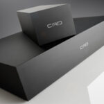
In other words, in certain instances, depending on the performance criteria of a given product, we can attach a plurality of networks to a given conductor. Sometimes cable size goes up simply because the performance criteria of that product dictate that we use a larger size conductor. Or in the case of the network box, maybe it is simply because we have chosen capacitors with a better (lower) dielectric constant (DK) and the capacitors will therefore become larger in size. I touched on this within my response to your DK question earlier.
20. In all of the discussion of MIT products I see no mention of Skin Effect. Is this considered by MIT to be a negligible element of cable design and construction? If not, how is Skin Effect treated?
I tend not to use the term Skin Effect, and tend to us the term Equivalent Skin Depth as I indicated earlier. This is because the term Skin Effect has different meanings to different people, while the term Equivalent Skin Depth usually only has one meaning to most people. Then again, the even more confusing fact is that some consider the terms to mean the same thing!
As I indicated earlier, Equivalent Skin Depth was a design criterion that I used back in the late 1970’s. This in fact was the technology that I licensed Monster Cable with in 1981. I still consider it meaningful, and I still use multiple gauge wires, wound at different intervals to optimize the effects of Equivalent Skin Depth in my higher-end designs.
Generally speaking, I define Skin Effect this way: Because high frequency signals do not penetrate well into high quality conductors, the resistance associated with a conductor at these high frequencies will be higher than the DC resistance. This effect is known as ‘the skin effect’ since the high frequency current flows in a thin layer near the surface of the conductor.
Generally speaking, I define Equivalent Skin Depth this way: If the Equivalent Skin Depth is larger than the wire radius, then the equivalent AC resistance of the wire is no different than the DC resistance.
I guess one can pick their own poison on this one, Doug.
21. Why is the baseline on the graphs of Articulation/Frequency set at 50%? Why not establish a full -10 to 100 percent (theoretical) chart?
Because, if and when I decide to explain the measurement in more detail, I would then have to rescale the Charts. The measurement is scaled at 50% for a reason, we just have not released why it is scaled that way yet.
22. In my listening tests of the Oracle MA Digital cable the Articulation Response setting seemed overwhelmingly to influence the bass, which would seem to support my thought that the bass to mid-bass is predominantly the region most benefited by this technology. Is a stepped filter, or attenuation, being applied to the lower frequencies through use of the selector on this cable?
No, there is no stepped filter or attenuator that selectively emphasizes or de-emphasizes any frequency, or any band of frequencies for that matter Doug.
23. As I inspected the Z Powerbar I saw that some black permanent marker had blackened out what I read to be specs as, “10A” and “220V 10A 50-60Hz”. What is the significance of this? Was this model used in Europe and adapted to the U.S.? Is it manufactured in China and imported? Please explain.
The Z Powerbar is sold both in the USA as well as into many international countries. We have the chassis built and silk screened for both 230 Volt as well as 100-120 V applications. We then simply ‘black out’ the inappropriate application when we build the unit.
And no Doug, all of our power products are made right here at MIT in the good ole USA!
24. MIT uses the exchangeable termination system called “iConn”. With the use of the Magnum MA speaker cables there are three non-soldered connection points on the cables’ leads. Some audiophiles feel there is a loss of signal quality with such contact points. What would be your response to such a criticism?
Good question Doug. The answer to your question is a little bit more complex than a simple yes or no. First of all Doug, we have only added one extra connection, as the other two you are relating to are between the amp and input of the cable, as well as the speaker-to-cable connection located at the output of the cable. In this configuration, all audio cables possess those two connections.
As I spoke about earlier, all audio cables possess three electrical components, LC&R. The relationship between the measured responses of those three components can change what we hear regarding any cable or passive network.
So once again, let’s attempt to create a scenario to answer your question. Let’s imagine that I have designed a networked cable that had optimal LC&R values, and it sounds just great. Then I decide to cut it in half and add another connection in the middle. Now I can assure you Doug, the cable will not sound the ‘same’ as it did before we added the additional connection. However, if I go back and redesign the networks, and change the LC&R values so that they are optimized to work with that connection, then it will sound just as good as the original networked cable that did not have the extra connection.
The above is based on certain constants being rigidly maintained, such as uniform connector tightness, as well as the cleanliness of the connectors. But then again, this is no different than the maintenance of the other two connections.
25. What is the meaning of the phrase, “tuned LCR technology” which is discussed in relation to the Parallel AC filtering?
The Inductance (L), and the Capacitance (C) are tuned to resonate, thereby creating a specific impedance at a some particular frequency required by the product’s application. Usually the resistance (R) is used to either dampen the resonant filter and / or dissipate the noise that is passed through it.
26. Please describe in layman’s terms how the “parallel circuitry” in MIT power devices removes noise.
The “tuned LCR technology” that I just spoke about in your last question offers a very low impedance to all forms of extraneous noise above the 50-60 Hz power line frequency. Once the noise enters the filter, the filter absorbs it by turning it into harmless thermal heat via the filters ‘real’ resistance. These filters are not in series with the AC line. They are in parallel, or put ‘across’ the positive (hot / active) and negative (neutral / return) legs of the AC line.
Generally speaking, the term “series” deals with components that are connected end-to-end. And the term “parallel” means that components are connected side-by-side, or in shunt / across.
27. In relation to the ability of the Z Powerbar to condition the AC coursing through their system, one of the problems associated with dirty power, according to the MIT Z Series Power Products pamphlet is, “Digital data loss and errors”. Please explain how the Z Powerbar can restore such digital data and decrease errors.
The Z Powerbar does not restore any digital data proactively, Doug. What it does is to absorb and convert undesirable noise that is generated by digital processors into thermal heat. Digital products are known to send a very strong pulse back into the AC lines. Many call these distortions ‘digital hash’, and they can mask detail, destroy intertransient silence, as well as add an overall hardness to the sound.
Thank you for sharing your time and expertise in answering these questions!
MIT Cables: www.mitcables.com
